General
- Bondability of the coating
- Absence of varnish leakage between the laminations during the bonding process
- The floating roller test based on EN 1464 for quick bonding.
- For conventional bonding, bondability is tested using a floating roller test based on EN 1464 or a tensile lap-shear test based on EN 1465 (version with supported).
Floating roller test pursuant to IEC 1464
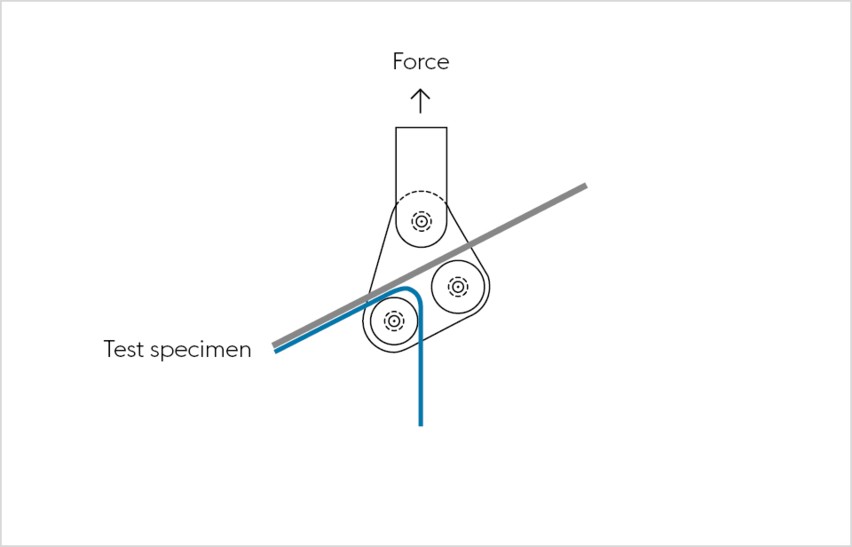
The floating roller test based on DIN EN 1464 determines the peel resistance of adhesives bonds. Two test specimens are bonded together, whereas one of the joined bodies must be flexible. A deflector roll on the tensile test machine separates the test specimen at a defined angle.
The floating roller test is an established testing method that provides useful results pertaining to the adhesive force as well as the strength and thickness of the steel strip used in the test setup.
Tensile lap-shear test
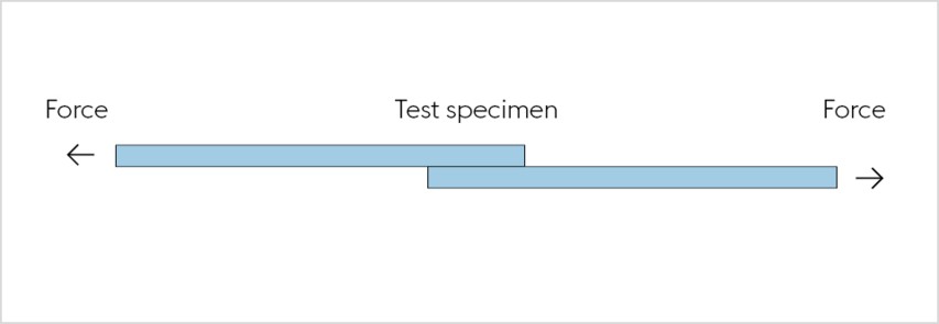
The tensile lap-shear test based on DIN EN 1465 also provides information about the strength of adhesive bonds. Once the test specimens are adhesively bonded, the test provides information about the quality of the bond. In contrast with the floating roller test, in this test the adhesive strength not dependent on the strength and thickness of the steel sheet.
The defined method used to assemble the stack is required as a basis for reproducible results when using each of the testing methods.
Using laser triangulation to evaluate varnish squeeze-out
Visual inspection of varnish squeeze-out between the laminations after bonding is dependent on several factors such as lighting conditions and the subjective assessment of testing personnel. That is now a thing of the past because voestalpine has developed a method for objective assessment and automated detection of varnish squeeze-out on bonded laminations.
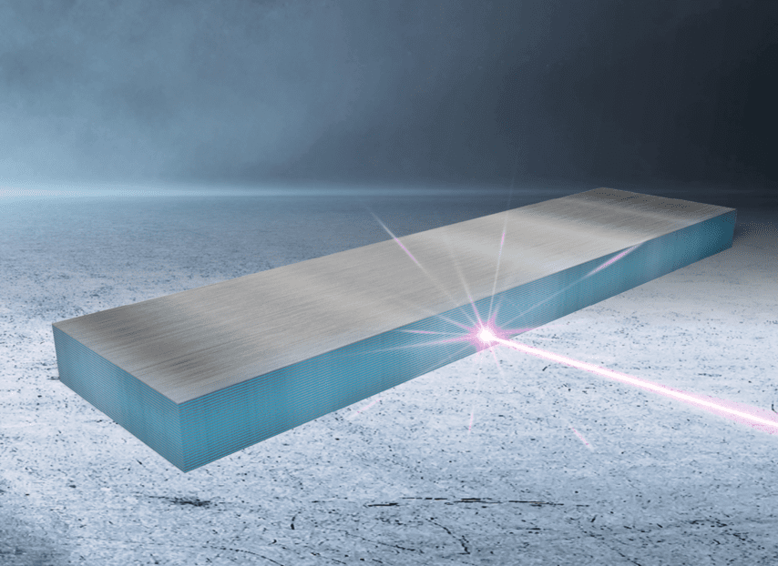
Laser triangulation is used to create a 3D point cloud on the front side of the bonded stack. Protrusions between the laminations may indicate varnish squeeze-out and are automatically detected, visualized and identified as defects.
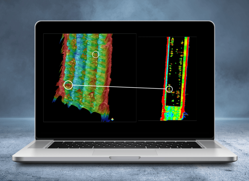
The major advantages of this assessment method compared to visual inspection by operating personnel are as follows:
- Automated, objective, quantifiable and reproducible determination of varnish squeeze-out between bonded laminations
- Reliable inspection of Backlack-coated material at voestalpine
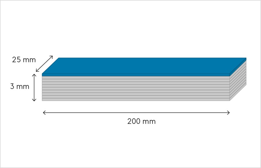
Production of test specimens
Test specimens are produced in compliance with EN 1464. The test specimen must measure 25 mm x 200 mm and be at least 3 mm high (regardless of sheet thickness). The long side of the individual laminations is positioned transverse to rolling direction.
Exactly one lamination is peeled from each test specimen, regardless of sheet thickness, using the floating roller device outlined in EN 1464.
Production of a roller peel test specimens
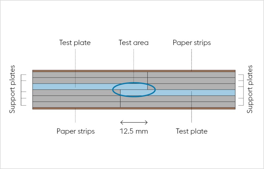
The geometry of test samples is selected pursuant to EN 1465
The tensile lap-shear test is performed in reinforced design for all strip thicknesses, whereas the actual component to be tested is reinforced with two layers of the same material. This serves to assess the actual quality of the bond and to prevent any plastic deformation or fracture of the joined component (see Figure 2). The overlap area is 12.5 mm by 25 mm (sample width). To avoid specimen deformation during the test, support plates must butt against each other. Any gap is not permissible.