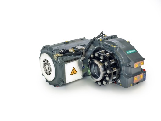
Best stacking factor without air inclusions.

Why is electrical steel important in the motor?
An electric machine can only function efficiently when its core is made of soft magnetic material such as electrical steel. Current-carrying coils generate magnetic fields that are amplified many times over by the electrical steel inside the coils, thus making operation of the motor much more efficient. The space inside the coils must be filled as densely as possible with soft magnetic material to ensure this amplification. A massive block of iron could theoretically be used for this purpose but would have the disadvantage of very high power consumption during operation. Stacks of thin, punched sheets are used in order to minimize the consumption of electricity.
What does the stacking factor entail, and how is it calculated?
The individual sheets are usually coated with an insulating varnish (typically 1–2 µm per side) and feature a certain degree of roughness. When the sheets are stacked and bonded, the stack consists of electrical steel, varnish coating and air inclusions. The ratio between the actual mass of the stack (total mass of the individual laminations) and its theoretical mass (if it were made only of steel) is the stacking factor. This is always less than or equal to 1, since the entire volume is never completely filled with iron.
Pursuant to the DIN EN 60404-13 standard, the stacking factor f is calculated as follows:

A pressure of 1 N/mm2 is exerted on the stack, and the stack height is measured:
A stacking factor of 0.97 means that 97% of the stack consists of electrical steel.
Which variables can influence the stacking factor?
Two variables have a decisive effect on the stacking factor: sheet thickness and coating thickness. Sheet surfaces are not completely smooth and feature a certain degree of roughness. Even when uninsulated material is used, the stacking factor is less than 1 because there are always air pockets between the laminations in the stack. The stacking factor is additionally reduced when coating layer thicknesses increase. The thinner the sheet is, the more pronounced the reduction in the stacking factor will be. The thicker the coating layer is on the strip surface, the less iron there will be in a stack of sheets of a given height. The thinner the electrical steel is, the less advantageous this ratio will become. (The ratio of sheet metal to coating thickness will become smaller and smaller.)
Consequence: Backlack with a typical layer thickness of 3 to 4 µm per side should be at a clear disadvantage when compared to C5 coatings with a layer thickness of 1 to 2 µm. This is not true!
Why does 3 + 3 not equal 6?
The small gap created by fillers (particles of up to a few µm in size) in C5 coatings and the roughness of the electrical steel strip is largely filled by Backlack during bonding, and the distance between the laminations is reduced. The stacking factor of the Backlack stack increases during the bonding process (a combination of temperature and pressure), which means that there is more electrical steel in the same space after bonding than before.
If fillers are used with Backlack—in contrast with C5 varnishes—the fillers have little or no effect on the stacking factor for the following reasons: Both the size and quantity of the fillers are smaller than in C5 varnishes, and the fillers are mobile during the bonding process, which means they can be easily distributed in uneven areas between the laminations in contrast with the fillers firmly anchored in C5 varnishes.

As the illustration shows, Backlack completely fills the area between the laminations after bonding, while there is still plenty of air between the laminations in a conventional insulation systems. Distance d between the laminations is comparable, even though there is much more varnish between the laminations in the case of Backlack. Any Backlack fillers can be distributed in the varnish matrix during the bonding process without increasing the distance between the laminations.
Measurements of the stacking factor on coated material show that this model applies: Electrical steel strip with a thickness of 0.35 mm coated with 3 to 4 µm of Backlack per side (6 to 8 µm total layer thickness) achieves the same or better stacking factor than material with the same thickness and coated with 1 µm C5 varnish per side (2 µm total layer thickness).

In addition to a high stacking factor, there are a number of other factors that have a positive influence on the performance of electric machines. One of these is the reduction of interlaminar eddy current losses, which is achieved by good electrical insulation between the laminations. The advantages of the Backlack coating come to bear again: Because of the high layer thickness, very high insulation resistance is achieved between the laminations, especially when baked (C state). Additionally, when the laminations are bonded, there are no points of contact such as weld seams or interlocking knobs, as is the case with other joining processes.
Conclusion
Backlack technology as a joining process for electrical steel stacks offers many advantages over conventional joining processes, such as freedom of design, mechanical stability and improved thermal conductivity (see https://www.voestalpine.com/isovac/en/Media-center/News/Backlack-the-joining-technology-for-perfect-lamination-stacks). The higher layer thickness of the Backlack coating increases insulation resistance, but negative effects on the stacking factor are often expected. This expectation, however, is not based on fact. Complete filling of the areas between the laminations during the bonding process ensures a very compact and dense core with a high stacking factor.